AVR Programming Guide
Make: AVR Programming by Elliot Williams (MAKE). Copyright 2014 Elliot Williams, 978-1-4493-5578-4.
Section titled “Make: AVR Programming by Elliot Williams (MAKE). Copyright 2014 Elliot Williams, 978-1-4493-5578-4.”-
Why using
Clanguage?- your code will be much faster (cycles and size)
- make the code flexible
Cis available for every CPUpuCwill work on every AVR
-
Micro controller is a whole computer on a chip, but it is very little computer
- CPU
- Dynamic memory
- Non-volatile memory
-
Tool chain
- life cycle of AVR programming :
write code in Cthencompile the code to machine languagethentransfer the code to the chipusing FTDI protocol, so we need a hardware between the AVR board and the PC
- life cycle of AVR programming :
-
What we need to begin
- cross compiler : GNU
avr-gcc>> for linux userssudo apt-get install avrdude binutils-avr avr-libc gcc-avr - hardware programmer
- AVRDUDE : knows how to run many hardware programmers
- a makefile to compile and flash in one step
- usb-serial converter
- cross compiler : GNU
-
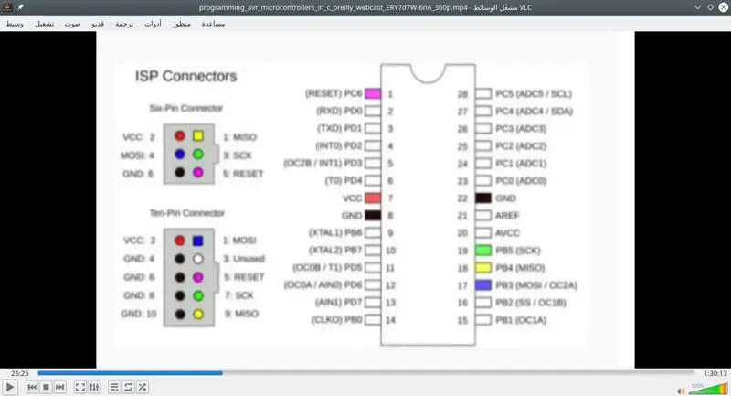
Hardware
- AVR uses the SPI interface for In-system programming (ISP)
- Wires need to hoock up
- Power
- Ground
- SCK (serial clock)
- MISO (Maser in Slave out)
- MOSI (Master out slave in)
- RESET (tell the AVR to enter programming mode)
-
Software
- Arduino ISP example, flash it to arduino
avrdude -p atmega168 -c avrisp -b 19200 -p /dev/ttyACM0 -nv- if it runs it will give info about board, if not recheck connections
- make file
- to setup the make file i have to define
- target MCU
- programmer
- serial port and speed
- make sure to open the make file in the same directory of the project
- to setup the make file i have to define
- open up terminal
- run
make flashormake program - type
maketo make the hex file - you can use
avrdude -p atmega168 -c usbtiny -U blinkLED.hex0Ravrdude -p atmega168 -c avrisp -b 19200 -P /dev/ttyACM0 -U blinkLED.hexdepending on the programmer-pchip type-cprogrammer type-Uhexfile file to upload
- it is better to personalize these values in your makefile and you can use it every time without type it again
// where your include information from other files #include <avr/io.h> #include <util/delay.h> // here we can also use define function. // or define globale variables int main(void) // the C code must have one main, here //where the AVR starts executing your code { DDRB = 0b00000010; // DDR, Data direction register sets pin one in PORTB (PB1) into output mode // can be DDRB |= (1<<PB1); while(1) // called main loop { PORTB = 0b00000010; _delay_ms(1000); PORTB = 0b00000000; _delay_ms(1000); } return (0); } -
there is another method to do that
#include<avr/io.h> #include<util/delay.h> #define led PB0 #define led_port PORTB #define led-ddr DDRB #define bv(x) (1<<x) #define setbit(p,b) p|=bv(b) #define clearbit(p,b) p&=bv(b) #define togglebit(p,b) p^=bv(b) ... in the main function setbit(led-ddr,led) ... togglebit(led-port,led) -
<avr/io.h> is the file that defines all the PORTs and DDRs.
-
<util/delay.h> provides us with the _delay_ms() function that we use to delay between blinks.
-
#define statements
- improve code readability and portability by defining constants or code fragments.
- For instance, in a setup with only one LED, I’ll usually define LED as a synonym for a particular pin on the AVR (PB0) partly to remind myself how to hook up the circuit, but also partly to make it easy to change later.
- For instance, if you were reproducing the blinkLED code, but you’d like to physically wire the LED to pin PB5, you could go through the code and change every occurrence of PB0 to PB5. If instead, as here, you define the LED pin at the top of the code, something like #define LED PB0 and then consistently only use LED in the main body, you’ll only have to change PB0 to PB5 in the one place where it’s defined, right up at the top of your code or in a suitably named include file.
-
Resgisters : fixed memory locations with side effects, can read and write like normal variables, each register byte is bits, each bit like a switch
- DDRx data-direction registers (port x) :
- These registers control whether each pin is configured for input or output the data direction.
- After a reset or power-up, the default state is all zeros, corresponding to the pins being configured for input.
- To enable a pin as output, you write a one to its slot in the DDR.
- PORTx port x data registers :
- When the DDRx bits are set to one (output) for a given pin, the PORT register controls whether that pin is set to logic high or low (i.e., the VCC voltage or ground).
- Switching between these voltage levels could, for instance, turn on and off attached LEDs.
- With the DDR configured for input, setting the PORT bits on a pin will control whether it has an internal pull-up resistor attached or whether it’s in a “hi-Z” (high-impedance) state, effectively electrically disconnected from the circuit, but still able to sense voltage.
- PINx port x input pins address :
- The PIN register addresses are where you read the digital voltage values for each pin that’s configured as input.
- Each PINx memory location is hooked up to a comparator circuit that detects whether the external voltage on that pin is high or low.
- You can’t write to them, so they’re not really memory, but you can read from the PINx registers like a normal variable in your code to see which pins have high and low voltages on them.
- DDRx data-direction registers (port x) :
-
bitwise operators :
-
ORbitwise : if i want to turn onPB1andPB2ledS i should consider the following :0b00000010 = (1<<PB1) 0b01000000 = (1<<PB7) 0b01000010 = (1<<PB1) | (1<<PB7)- For each bit position, a bitwise OR returns 1 if either bit in the comparison is 1. OR returns a 1 if this bit is 1 or that bit is 1. OR returns 0 only
- when both bits are 0:
1010 |1100 =1110 -
XORbitwise : if i want to change the status of one led i should use this operator as follows :0b00001111 ^0b00000010 0b00001101- XOR (or “exclusive or”) returns 1 if only one of the two bits compared is a 1. If both bits are 1 or if both bits are 0, XOR returns 0:
1010 ^1100 =0110 -
ANDbitwise : if i want to clear a specific bit like :0b00001111 &0b11111101 0b00001101Bitwise AND compares two bits and returns 1 only if both of the bits are 1. If either of the bits are 0, AND returns 0:
1010 &1100 =1000 -
NOTbitwise : also to clear bit :0b11111101=~(1<<PB1)- NOT takes all the bits and flips their logical sense —each 1 becomes a 0 and each 0 becomes a 1.
- It’s also the only logical operator that takes only one input:
~1100 =0011 -
so the approperiate way is :
PORTB = PORTB & ~(1<<PB1) OR PORTB & = ~(1<<PB1) -
to set bit :
PORTB | = (1<<PB1) -
to clear bit :
PORTB & = ~(1<<PB1) -
to toggle bit :
PORTB ^ = (1<<PB1)
-
-
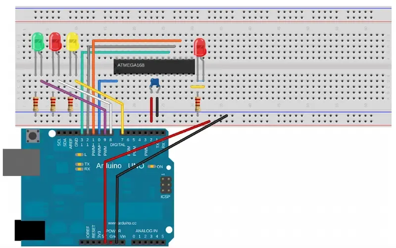
MOSFET trickery
- if you want to program an avr chip and there are loads connected to it, so we can use mosfet to control the conductivity of the ground terminal of the loads
- the AVR uses its RESET pin to enter programming mode.
- the RESET pin (PC6, blue wire from the programmer) is held at 5 V by the AVR when the chip is running, and pulled low to 0 V by the programmer to signal the AVR to enter programming mode.
-
PORTB = (1<<PB1) = (1<<1) -
The _BV() Macro : -The _BV() macro is just our bit-shift roll in disguise.
- In fact, it’s even defined as:
#define _BV(bit) (1 << (bit)) - So should you use _BV(2) or (1 << 2)? Well, theyend up being exactly the same thing.
- In fact, it’s even defined as:
-
different ways to toggle leds pattern
PORTB =(1<<i),PORTB = ~(1<<i),PORTB |= (1<<i),PORTB &= ~(1<<i) -
Setting Bits with OR
- set an individual bit in a register, leaving all the other bits as they were.
PORTB |= (1 << 2);
-
A bitmask :
- is just a normal old byte, but we’re thinking of it as being made up of ones and zeros in particular places that we specify rather than representing a numerical value.
- We use a bitmask, along with a bitwise logical operator, to change some bits in a target byte.
- I like to think of bitmasks almost like stencils used for spray painting. You cut away parts of the stencil where you want to change (paint) the underlying surface, and you leave the stencil intact where you don’t want paint to go.
- In particular, if we want to turn on some bits in PORTB while leaving the others untouched, we’ll create a bitmask with ones in the bit locations we’d like turned on. This works because a one ORed with anything will return a one. So we read in PORTB and OR it with the bitmask. The result should be the unaltered contents of PORTB everywhere that we had a zero, and ones everywhere our bitmask had a one.
- If we write this back out to PORTB, we’re set—PORTB has all its old bits intact, except those where there was a 1 in the bitmask have been turned on.
-
Toggling Bits with XOR
- Now imagine that you want to flip a bit or two. You don’t really care if it’s on or off right now, you just want it in the other state, whatever that is.
PORTB ^= (1 << 2);- for short. You can, of course, toggle more than one bit at once with something like:
PORTB ^= ((1 << 2) | (1 << 4));
-
Clearing a Bit with AND and NOT
PORTB &= ~(1 <<2);(1 << 2) -> 0b00000100 ~(1 << 2) -> 0b11111011 ```PORTB & = ~(1<<3);
-
uint8_t: unsigned int 8 bits -
uint16_t: unsigned int 16 bits -
uint8_t: from 0 to 255 if the maximum value255is reached it will count from the begining0again -
serial communication
serial protocol: The rules for encoding data into voltage pulses and decoding the voltage pulses back into dataUARTserial : universal asynchronous receive and transmit is the most common serial mode- To understand what’s going on with UART serial, start by thinking of two people who want to talk to each other by sending voltage signals over a few wires.
- Let’s say Alice wants to send the number 10 to her friend Bob over a wire.
- For concreteness, let’s say that the wire’s got a pull-up resistor on it so that it’s constantly at five volts.
- On Alice’s side of the wire, there’s a switch connected to ground, and on Bob’s side, there’s also an LED so that he can see what the voltage on the wire is by whether or not the LED lights up.
- Alice is going to send the number 10 to Bob by pressing her button, grounding the wire, and turning off Bob’s LED on the other side.
- Now, she could send the number by just blinking the LED off 10 times, but that system’s going to break down when she wants to send the number 253, or worse, 64,123.
- So instead she writes out 10 in binary, 0b00001010, and sends a corresponding pattern of flashes.
- Bob and Alice have to agree on a bunch of things beforehand for this to work the serial protocol.
- First they need to decide on an encoding: they agree before hand that a button press (a zero-volt signal on the wire) indicates a zero, and no press (five volts) indicates a one, and that they’ll send the numbers least-significant bit first.
- Next, they need to agree how often Alice presses or doesn’t press the button.
- Let’s say they choose to signal once per second.
- This is the baud rate—how often the voltage is allowed to change on the line, and conversely how often the receiver needs to read in a new voltage.
- How does Bob tell when the transmission begins and ends? They’ve agreed to wrap the eight bits with two extra bits: a start bit, which will always be a zero so that you can tell when the transmission starts, and a stop bit, which is a one.
- Bob is sitting at his end, staring at the LED, when he sees the LED blink. It blinks off for a second—the start bit! Now once every second after the start bit, he notes down whether the LED is on or off.
- After the first blink, he sees off, on, off, on, off, off, off, off, and then the LED stays on for a while.
- He writes down his eight bits, 01010000.
- He then flips the bit-ordering around, and sees that Alice has sent the number 10!
- The oscilloscope trace is a real example of an AVR transmitting the digit 10 to my computer.
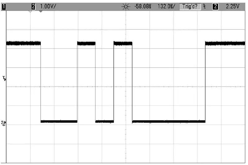
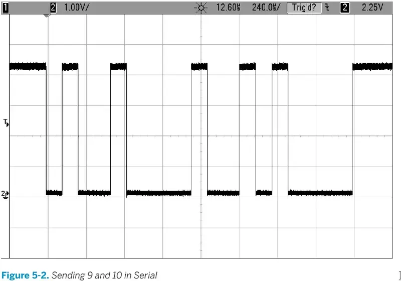
- Instead of one bit per second I used 9,600 bits per second (baud), so each bit takes about 104 microseconds.
- Encoding and decoding this data seems like a lot of work, and getting the timing exactly right to send and receive data at baud rates in the tens of thousands of bits per second is no picnic either. That’s why all of the AVR Mega microcontrollers have at least one dedicated hardware peripheral, called a Universal Synchronous and Asyncronous Receiver and Transmitter (USART) device built in.
- Connecting your serial adapter to the AVR is as simple as connecting three wires, and the first one’s simple:
- iit’s GND. The other two are “tricky.” You need to connect the RX of one device to the TX of the other, and the TX of one to the RX of the other.
- When a capacitor is subject to a DC voltage, it lets a little current through until it is “charged up” to that voltage, then it blocks further current. This means that capacitors pass current only for changes in voltage. This is perfect for our speaker!
- The changing signal that makes up the audio is passed through, while the speaker doesn’t overload the AVR’s output current when the voltage is held high.
- But do note that if you’re using an electrolytic capacitor (one that comes in a metal tube-shaped can), they often have a positive and negative sides to them. We’re not running enough current through the capacitor to damage it anyway, but you might as well hook it up with the stripe (negative terminal) to ground.
- Python is an interpreted language, and includes modules that let you do basically anything, easily.
- I’ll use it throughout the book for projects that require computer/AVR interaction, or for doing any sort of computations that are too demanding for the AVR.
- Choose a baud rate, here by defining BAUD, and write the appropriate values to the baud rate registers UBRRL and UBRRH. (The setbaud.h library will help you with this.)
- Enable the serial receive and transmit register bits.
- If you’re transmitting, wait until the hardware is ready (loop_until_bit_is_set(UCSR0A, UDRE0)) and then load your byte data into UDR0. The AVR’s hardware handles everything else automatically.
- If you’re waiting for data, check the data-received bit (bit_is_set(UCSR0A, RXC0)) and then read the data out of UDR0. Reading UDR0 automatically clears the data-received bit, and the AVR gets ready for the next received byte.
-
push button
- Push buttons are cheap, ubiquitous, and the natural choice for quick and mostly painless human/AVR interaction.
- The naïve circuit shown connects one end of the pushbutton to ground and the other end to the AVR That way, whenever you press the button the AVR end is connected to ground, too, so it’s pretty much guaranteed to be at 0 V.
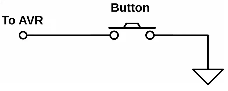
- But when you let go of the button (or open the switch), what is the voltage at the AVR end of the switch? Short answer: nobody knows. A wire that’s just dangling in the air, on the unconnected side of a switch, can act as an antenna.
- The voltage on that wire will wiggle around between high and low logic states at whatever frequency the strongest local radio stations (or even “noisy” electrical appliances) broadcast.
- Instead of some random value, you want the side of the button that you connect to the AVR to have a nice, defined high voltage level when the button isn’t pressed.
- But you can’t hook the AVR-side of the button directly to VCC, because if you did, you’d be shorting out the power supply when you pressed the button—hooking VCC up directly to GND is a recipe for disaster. Enter the pull-up resistor
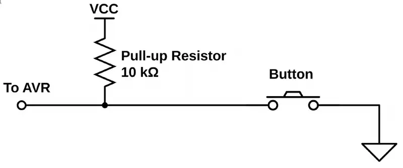
- Now here’s the cool bit. The AVR chips provide you a built-in pull-up resistor for each pin, and you have the option to activate it for any pin that is in input mode.
- to set a pin to be input and to enable pull-up resistor of this pin
DDRD &= ~(1 << PD2);PORTD |= (1 << PD2);
- how to test an input pin
- Testing bit states is done with the AND operator.
- You know that an AND will only return 1 if both bits are 1.
- If you perform an AND operation in which you compare an unknown bit value against a known 1, you’ll get the state of the mystery bits as the result.
- So you’ll bit-shift a 1 into the bit location you’re interested in, then AND the two bytes together.
- The result will either be all zeros if the target bit was zero, or it will be a byte with a 1 in the target location if it was 1.
- Say we’re interested in testing if bit two is set. The first step is to create a bitmask with a 1 in bit two:
(1 << 2) : 00000100
- Then we AND that byte with whatever is in the input register, PIND:
PIND : xxxxxxxx(1 << 2) : 00000100& : 00000x00
- If the value we were interested in knowing is a zero, the result is eight zeros.
- If the result isn’t zero, then we know the pin in the input register must have been set.
- So we can test this:
if (PIND & (1<<2))
{
    doStuff();
}
- to solve bounce button problem :
- using capacitor
- using delay
- variable to store the button status
- using python to write script on computer, because it’s very easy to extend your work from one domain to another. Most of the stuff that’s almost impossible to implement on a microcontroller is trivial in Python (and vice versa).
-
i should check that site for newly added stuff
-
search for bruce land’s cornell university engineering course